Building ISERink
This section will detail the steps to install ESXi, configure the virtual networks, install the virtual machines, and configure ISERink.
Downloading and installing VMware ESXi
Overview
The first step in building ISERink is to install and configure VMware ESXi to host the various virtual machines on a single server. If you need instructions for installing ESXi you can find help on the VMware website. Many of the screenshots in this document are of VMware ESXi 5.5 and the exact images may be different depending on the version used.
In this section, you will download and install ESXi onto your server. ESXi is a bare-metal hypervisor that provides a lightweight framework for virtual machines to run on. ESXi allows virtual networks to be created inside of it with numerous virtual machines.
Your machine running ESXi will use one of the network interfaces for remote management. During installation, you will need to give this interface an IP address. The management interface can be on the public Internet or you can place it behind a NAT and/or Firewall (see “ISERink Internet Access”).
Download ESXi
First, download the image for ESXi 5.5 or higher from VMware’s web site. As of writing, the latest version is ESXi 6.5, which can be obtained from VMware’s Download Center. Before the image can be downloaded, you must create a free account with VMware and log in. After logging in, download the ISO image for ESXi. Also note that near the top of the page is the license key that you will need to register ESXi. It is easiest to burn the ISO onto a CD or USB drive and boot your server from the CD or drive to install the software.
Warning
This guide has not been fully changed ESXi 6.5 and some parts may need to be changed for ESXi 6.5.
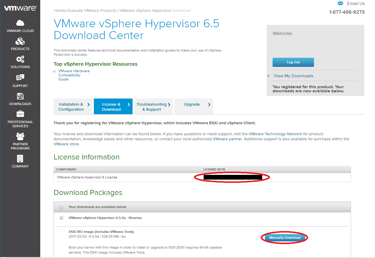
Fig. 7 Location of ESXi key and ISO download
Install ESXi
After downloading the ESXi ISO image, install ESXi on your server (the default settings are fine). If you need further information on installing ESXi, you can find information online or on the ESXi website. The most common problem is not having ESXi compatible hardware. The VMware website has compatibility guides to help determine if your hardware is compatible. During the installation process, you will need to create the root password for the ESXi hypervisor. The root password for the ESXi is used to manage the ESXi system and should not be shared with general users. After ESXi has been installed, you will be presented with a screen which looks similar to Fig. 8.
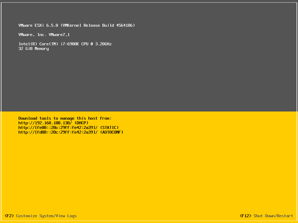
Fig. 8 ESXi main screen
Map Network Interfaces on ESXi
After installing ESXi, one of the first things that should be done is to map and label the physical network adapters (NICs) on the server. To do this, you will individually hook up the physical NICs to a switch or router and see which interface shows as active in ESXi. First, press the F2 key to enter the ESXi configuration page. Enter your root password and then press Enter.
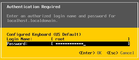
Fig. 9 ESXi password prompt
Use the arrow keys to select Configure Management Network as shown in Fig. 10 and then press Enter.
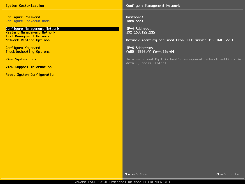
Fig. 10 Configure management network
Press Enter to select Network Adapters. You will then be presented with a screen that looks similar to Fig. 11.
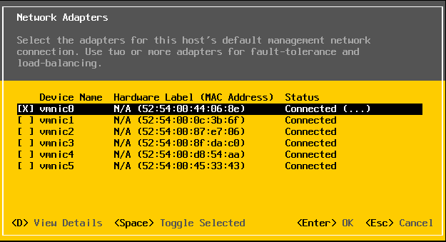
Fig. 11 ESXi network adapters
If any of the NICs are currently connected to anything, the status for that NIC will show up as connected on this screen. One by one, hook up NICs on the server to either a switch or a router. Exit out of the Network Adapters dialog box by pressing the Esc key and then re-enter the Network Adapters dialog box by pressing the Enter key. The Network Adapters dialog box should now show a different VMNIC as connected. Repeat this process for all of the NICs on the server and either write down the NIC mapping or label the NICs on the server. You will need this information later to properly connect the server. You can use the table in Appendix A to fill in what you discover.
Configure Network Settings
Next, an IP address must be assigned for the management port. The IP address of the management port is needed to remotely manage the ESXi system. The worksheet in Appendix A can be used to write down this information for future reference. From the Configure Management Network screen, use the arrow keys to select IPv4 Configuration and hit Enter. You will then be at a screen that looks similar to Fig. 12.
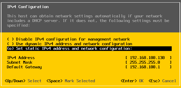
Fig. 12 IP address configuration
Use the arrow keys to highlight Set static IP address and network configuration and hit Spacebar to select it. Fill out the IP address for the management port, subnet mask, and default gateway then hit enter. If you do not know what to put here, contact your network administrator.
From the Configure Management Network screen, use the arrow keys to select DNS Configuration and hit Enter. You will then be at a screen that looks similar to Fig. 13.
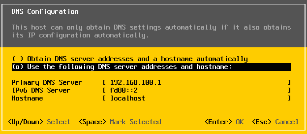
Fig. 13 DNS Configuration
Use the arrow keys to highlight Use the following DNS server addresses and hostname and hit Spacebar to select it. Fill out the primary DNS server, Alternate DNS server, and Hostname, followed by pressing Enter. If you do not know what to put here, contact your network administrator.
Enable remote management of ESXi
In order to download the ISERink images, you will need to use the command line interface of the ESXi hypervisor. This can be done two ways. Either you may use the ESXi shell, or you may remotely access it via SSH [2]. One or both options must be enabled. To enable these options, you need to enter the ESXi configuration page as shown in Step 3.1.3. The options are enabled by selecting the menu item Troubleshooting Options as shown in Fig. 14.
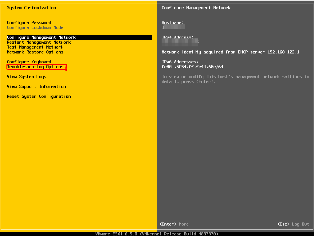
Fig. 14 Troubleshooting Options
There you will see an option Enable SSH and an option Enable ESXi shell, see Fig. 15. Once enabled, you can access the command line interface. (You will do this later.)
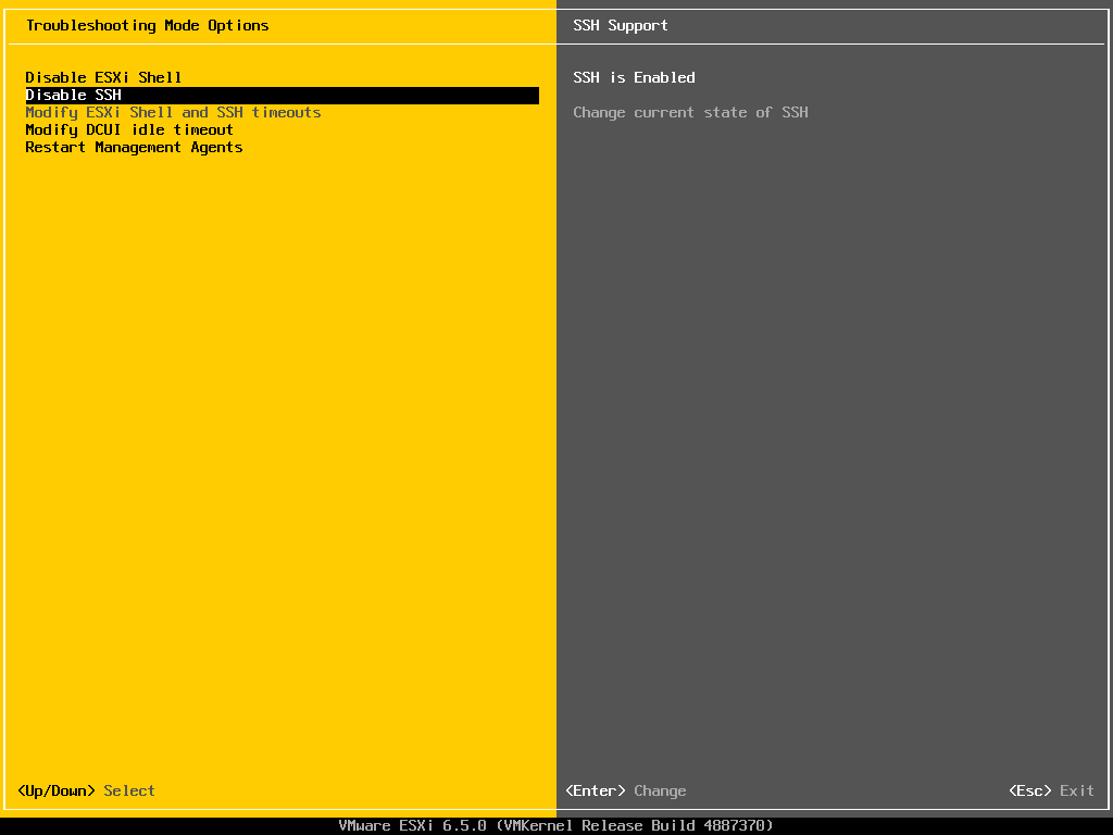
Fig. 15 ESXi remote access
To access the command line interface using the ESXi shell you need to press Alt+F1 on the keyboard connected to the ESXi machine. This will bring up a UNIX login prompt and you can enter the username: root and the root password. If you choose to use SSH you will need an SSH client on the PC you are using to manage ESXi.
| [2] | If SSH is exposed to the public Internet, you will certainly experience malicious login attempts. Ensure you have chosen a strong password and have locked down the SSH service using ESXi’s firewall or your system may become compromised. |
Configuring ESXi
To configure ESXi, you must first download and install the vSphere Client (runs on Windows only). To do this, on a separate Windows machine that is on the same network as the server, open a web browser and navigate to the downloads page for the vSphere Client. Download the version corresponding to your version of ESXi.
Note
With vSphere 6.5, the VMware vSphere Desktop client is deprecated in favor of the web client. The vSphere Client 6.0 currently partially works with ESXi 6.5. These directions may need to be adapted, if you choose to use ESXi 6.5 with the web interface instead of the vSphere Client.
After the vSphere client is downloaded, install it. After installing the vSphere Client, run the program. You will be presented with a window similar to Fig. 16.
Note: The machine used to configure and manage ISERink needs to be able to access the same network that the ESXi management port is located. See “ISERink Internet Access”.
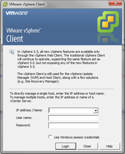
Fig. 16 vSphere Client login window
Enter the IP address of your ESXi server (Fig. 8). The username is root, and the password is what you chose when setting up the ESXi server. You need to ignore the certificate warning and optionally install the certificate to avoid future warnings. After logging into vSphere, you should see a screen similar to Fig. 17
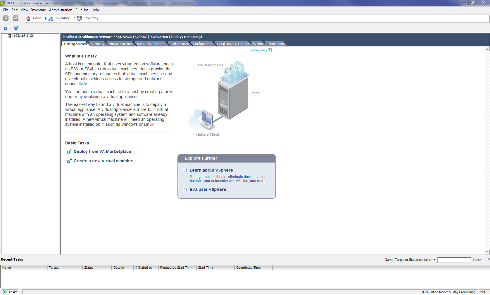
Fig. 17 vSphere Client main window
After logging into the vSphere Client, the first thing to do is to install the vSphere license key.
ESXi License Key Registration
- After logging into the vSphere Client, go to the Configuration tab.
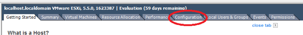
Fig. 18 vSphere Configuration Tab
2. Next, click the Licensed Features link inside of the Software box on the left side of the screen Fig. 19.
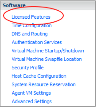
Fig. 19 Software -> Licensed Features
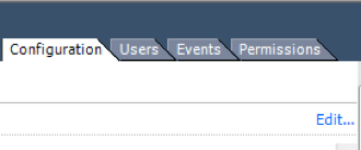
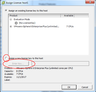
Fig. 21 Enter license key
- Enter your license key in the box and click the OK button.
Enable outbound SSH
In order to copy the VM images to your ESXi server, you will need to enable outbound SSH through the ESXi firewall. This is done through the security profile menu as shown in Fig. 22. Click on the Properties… link on the firewall section. Check the box for the SSH client, then click OK. As seen in Fig. 23.
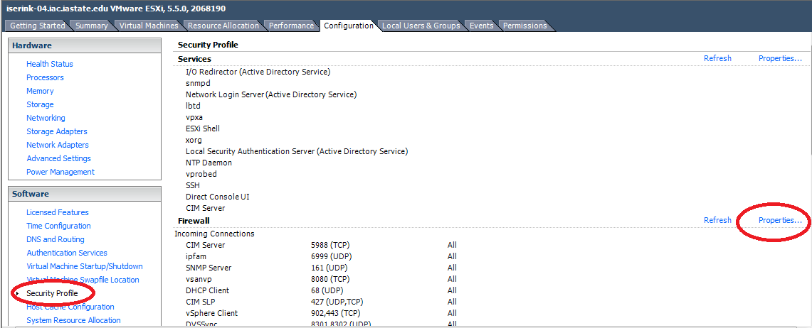
Fig. 22 Edit firewall
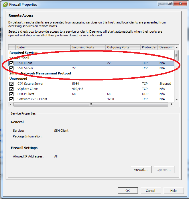
Fig. 23 Turn SSH Client on in the Firewall
Setting up the ESXi Virtual Networks
In this section, you will create the virtual networks needed for ISEAGE.
Note
At this point, there is a shortcut we can take to make the installation process faster. A script is provided to automate some of the configuration. If you would like to learn more about ESXi and the networking setup, the networks can be configured by hand without the script.
- Proceed to Download Virtual Machines to download and decompress the images.
- Run the script by running the command sh /vmfs/volumes/datastore1/esxi_setup.sh from the ESXi console or SSH.
- Continue with the documentation from Configure Snowbank, Snowflake, Keyhole1, LDAP, and IScorE.
Warning
The script assumes you are using the suggested configuration of 6 physical network interfaces on your server. If you do not have 6 physical network interfaces, this script will error and not set up the physical networking correctly. However, this script will configure all internal networking correctly regardless of your physical configuration. If you decide to use this script anyway, review Table 1 after running the script to make sure your networks are set up correctly.
ESXi Virtual Network Configuration
In this section, the virtual network will be created to provide the foundation to connect the various components of ISEAGE. It is important that you name the virtual switches exactly as shown in the directions. This is so the virtual machines will automatically connect when they are imported.
Important
These instructions are written assuming 6 physical network interfaces on your server. If your server doesn’t have 6 physical network interfaces, then you will need to decide how to best utilize the physical NICs for your ISERink installation.
Alternative Configurations
If there are less than 6 physical network connections on your server, here are some solutions on how to get by with the fewest issues. Configured correctly, an ISERink can use fewer physical network connections with limited impact:
- Blue-2: Blue-1 and Blue-2 both provide 15 /24 subnets. If less than 15 subnets will be used, then Blue-2 does not need to be on a physical network connection. If this is done, then users must make sure the subnets they are using are on Blue-1. Since Blue-2 will not be available outside the physical machine.
- VLANs can be used to reduce required NICs down to a minimum of 1 (although more than 1 may be desired for performance). Any network needing a physical connection can be created as a virtual port group and attached to a NIC-connected vSwitch, with an arbitrary number of port groups being possible on each vSwitch. This setup is more complex and requires knowledge of configuring VLANs both in ESXi and your existing environment.
TAP
The TAP port is used to listen to all communications in the ISERink, if you do not plan on using this for traffic analysis or packet captures, this does not need to be mapped to a physical network connection. This will have no effect on the ISERink’s operations.
Configure External Network
- In the vSphere client, go to the Configuration tab.
- Click on the Networking link in the Hardware box on the left. The initial configuration will look similar to Fig. 24.
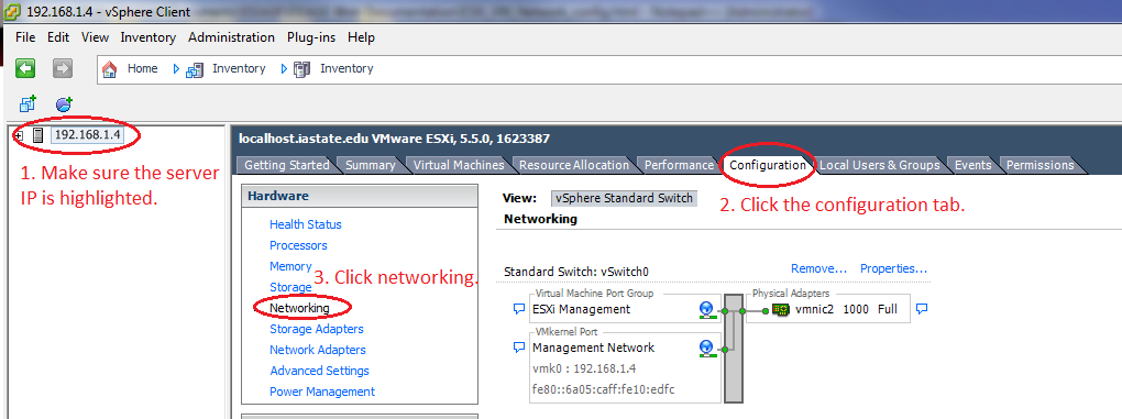
Fig. 24 Network Configuration Section
- Click on the Properties… link next to vSwitch0. See Fig. 25
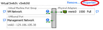
Fig. 25 Initial Network Configuration
- Highlight the second item in the list on the left (the name of the vSwitch) and then click the Edit… button. See Fig. 26.
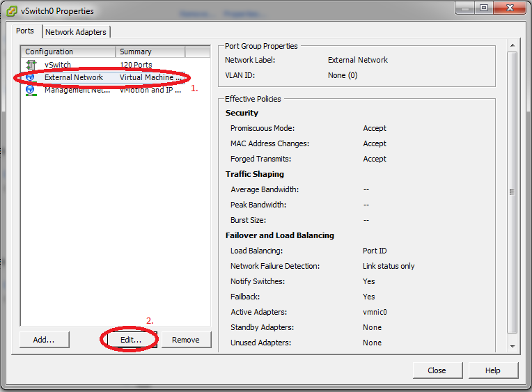
Fig. 26 Edit vSwitch Name
- Change the name of the vSwitch to be “External Network”, click OK, and then click the Close button on the vSwitch properties window. See Fig. 27.
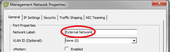
Fig. 27 Change vSwitch Name
Add the other vSwitches
- Now, click on Add Networking… to create a new vSwitch. See Fig. 28.
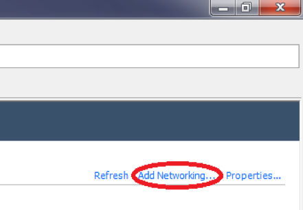
Fig. 28 Add vSwitch
- Click Next to create a Virtual Machine type switch. See Fig. 29.
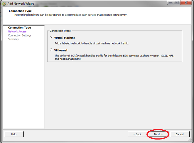
Fig. 29 Create a VM Switch
- Make sure all of the physical network connection (vmnicX) boxes are unchecked for this switch to create a purely virtual switch and then click Next.
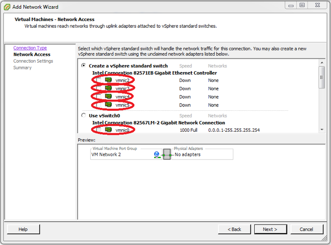
Fig. 30 Edit vSwitch Physical Connections
- Name the switch “Air Gap”, click Next, and then click Finish on the next screen.
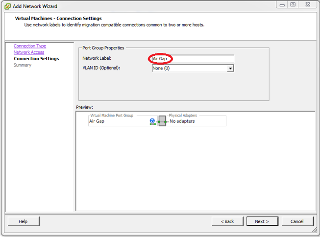
Fig. 31 Name the vSwitch Air Gap
- Your virtual network layout should now look similar to Fig. 32.
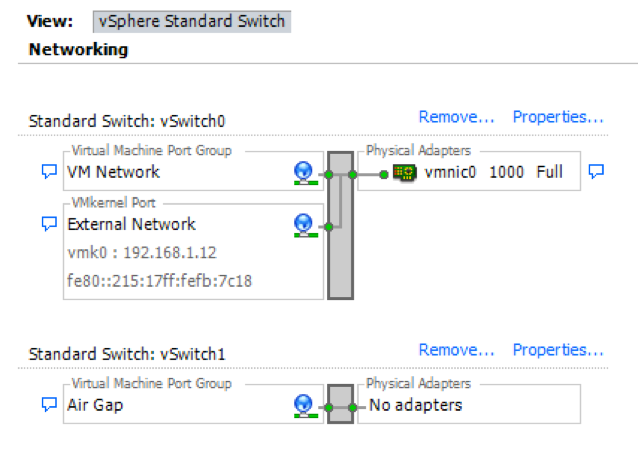
Fig. 32 Network layout
- Repeat steps 1 through 5 to create all of the switches shown in Table 1 to create the Virtual Network for ISEAGE. Do not worry about the promiscuous column for now. We will take care of this in the next step.
| Name | Network Label | Promiscuous | Network Adapter (Vmnic) |
|---|---|---|---|
| vSwitch0 | External Network | No | Vmnic0 |
| vSwitch1 | Air Gap | No | None |
| vSwitch2 | Backplane | Yes | None |
| vSwitch3 | Control | Yes | None |
| vSwitch4 | Keyhole | Yes | Vmnic1 |
| vSwitch5 | Blue-1 | Yes | Vmnic2 |
| vSwitch6 | Blue-2 | Yes | Vmnic3 |
| vSwitch7 | Red-green | Yes | Vmnic4 |
| vSwitch8 | TAP | Yes | Vmnic5 |
| vSwitch9 | Ice Bridge | No | None |
| vSwitch10 | pfSense WAN | No | None |
| vSwitch11 | Private Net | No | None (optional) |
- Now we will go back through the switches we just created and enable promiscuous mode.
Note
ISERink will not function if this is not configured properly!
- Click on the Properties... link next to vSwitch0 See Fig. 33
Fig. 33 Initial Network Configuration
- Make sure that the vSwitch is highlighted and then click the Edit… button. See Fig. 34
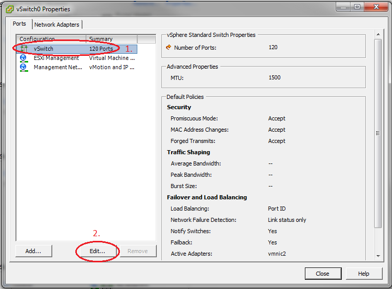
Fig. 34 Switch Settings
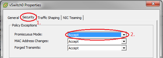
- Go to the Security tab and change Promiscuous Mode to Accept and then click OK. See Fig. 35
Downloading and Installing the Virtual Machines for ISERink
In this section, we will download and install the virtual machines to build ISEAGE. All network connections should automatically be made if the networks are configured correctly.
Download Virtual Machines
- Log into the ESXi machine using either the ESXi console or using SSH. The figures shown in this step are from using SSH to access the ESXi server.
- Once you have logged into the system change into the directory that holds
the datastore as shown in Fig. 36. using the command
cd
/vmfs/volumes/datastore1
Fig. 36
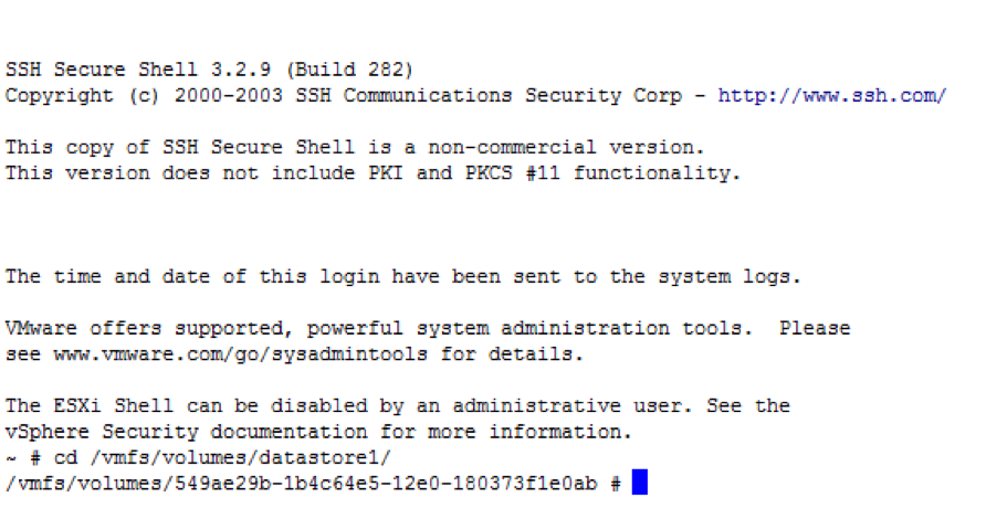
Fig. 36 Change directory to the datastore
- Copy the virtual machine images from the repository isechest.iac.iastate.edu using the SCP command as shown in Fig. 37. The total size of the images is about 10GB in size, so the transfer make take some time.
Note
Use the username and password provided to you when you registered to get access to ISERink.
scp "USERNAME@isechest.iac.iastate.edu:/home/downloads/ISERink/v1" .
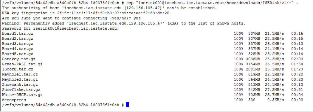
Fig. 37 Copying files from isechest.iac.iastate.edu
- Once the files have been copied, there will be several compressed tar files and a shell script called decompress. Note the decompression may take several hours. Type the command:
sh decompress.sh
Install the Virtual Machines
- As described in Overview of ISERink, ISERink consists of multiple interconnected virtual machines. Table 2 lists the virtual machines and the virtual networks they are connected to.
| Machine Name | OS Type | Adapter 1 | Adapter 2 | Adapter 3 |
|---|---|---|---|---|
| Snowbank | pfSense | External Network | Ice Bridge | |
| Snowflake | FreeBSD | Ice Bridge | Control | Backplane |
| Gatekey | FreeBSD | Ice Bridge | Control | |
| Keyhole1 | FreeBSD | Keyhole | Air Gap | Control |
| Keyhole2 | FreeBSD | Ice Bridge | Air Gap | Control |
| Board 1 | FreeBSD | Blue-1 | Backplane | Control |
| Board 2 | FreeBSD | Blue-2 | Backplane | Control |
| Board 3 | FreeBSD | Red-green | Backplane | Control |
| Board 4 | FreeBSD | Keyhole | Backplane | Control |
| Board 5 | FreeBSD | TAP | Backplane | Control |
| IScorE | Debian | External Network | Private Net | Keyhole |
| Green-KALI | Kali Linux | Red-Green | ||
| White-DHCP | pfSense | pfSense WAN | Keyhole |
- After copying and uncompressing the virtual machine images, we need to open up the datastore browser on ESXi. First, log into ESXi, if not logged in already, then go to Configuration then Storage and right click on your datastore, and then go to Browse Datastore…. See Fig. 38.
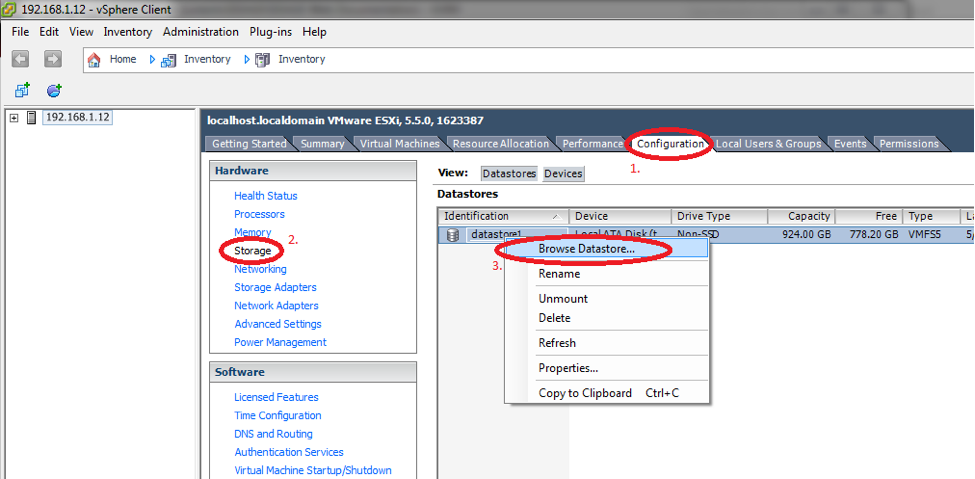
Fig. 38 Browse Datastore
You must add all of the VMs to ESXi. To do this, click on one of the VM folders. Then find the virtual machine file (ending in .vmx), and click it to highlight the file. Then click on the button in the upper left corner of the Database Browser window to add the virtual machine to the inventory. A window will open. Leave the virtual machine name alone and click Next. On the following page, also click Next. On the final page, click Finish. See Fig. 39.
Repeat this step for all of the virtual machines.
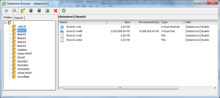
Fig. 39 Add VM to Inventory
After importing all the virtual machines, we need to power them on. To power on a virtual machine, select it from the left pane of the vSphere Client’s main window. Then click Power on the virtual machine (see Fig. 40). If a prompt asks if the virtual machine was moved or copied, see the next step.
Power on virtual machines in this order:
- Snowbank
- Snowflake
- Keyhole1
- Keyhole2
- Board 1
- Board 2
- Board 3
- Board 4
- Board 5
- IScorE
- Gatekey
- Green-KALI
- White-DHCP
Important
Power on the virtual machines in the correct order. (We will later set ESXi up to power them on automatically.)
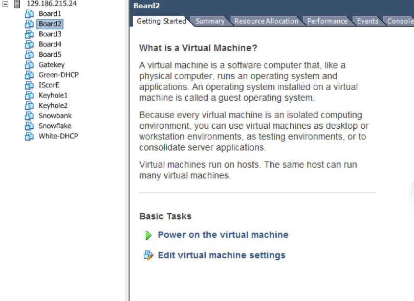
Fig. 40 Power on each VM
A window may pop up asking if you moved or copied the Virtual Machine. Check the Copied it option and then click OK as seen in Fig. 41. Alternatively, you may see the question icon next to your virtual machine name in this case you will have to go to the virtual machines setting tab and check the Copied it option and then click OK as seen in Fig. 42.
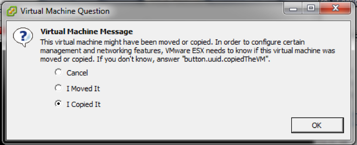
Fig. 41 VM First Boot Message
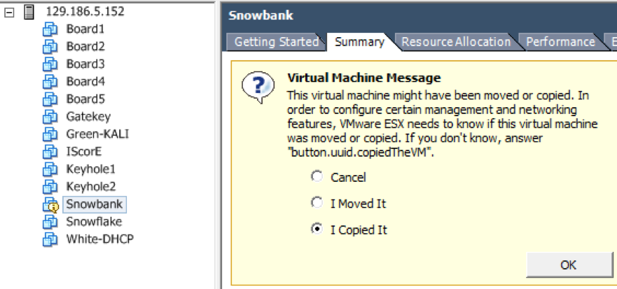
Fig. 42 VM First Boot Message
At this point, all of the virtual machines should be installed and configured correctly. Next, we are going to configure the auto-start feature of ESXi to start up the virtual machines in the correct order whenever the physical server is powered up.
Configure Auto-startup
- In this section, we will configure the virtual machines to automatically start up in the correct order when the physical server is started. Go to the Configuration tab, click on Virtual Machine Startup/Shutdown and then click Properties. See Fig. 43.
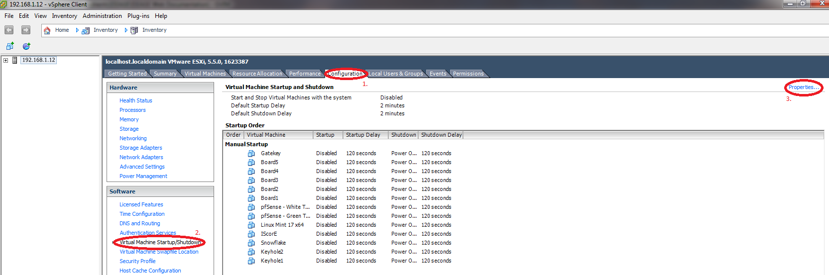
Fig. 43 VM Startup/Shutdown Configuration
- In the configuration window which opens up, check the two options in the upper left side of the window. See Fig. 44
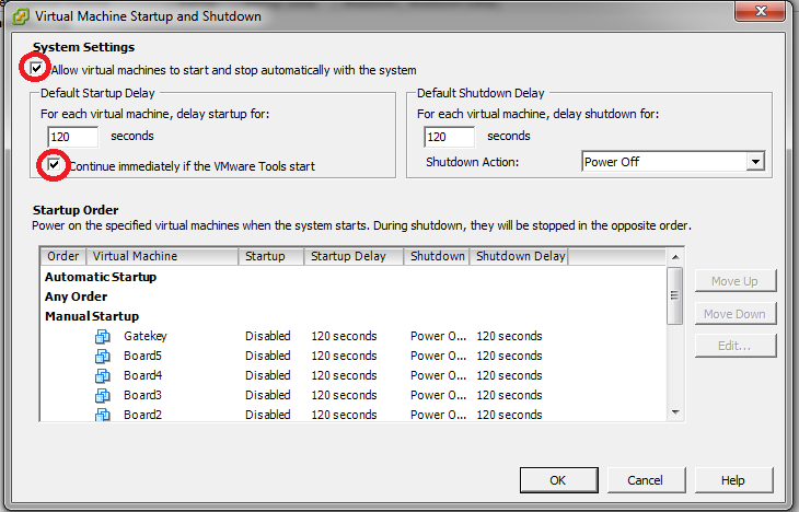
Fig. 44 VM Startup/Shutdown Options
- Now we will configure the order in which the virtual machines will start up. First find the Snowbank Virtual Machine and click it to highlight it. Now, repeatedly click on the Move Up button to move the Snowbank VM into the Automatic Startup section. See Fig. 45.
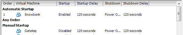
Fig. 45 Snowbank Auto Start
- Continue this process for the rest of the VMs until the startup order is the same as in Fig. 46.
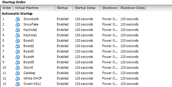
Fig. 46 Figure 3.3.11: Startup Order
Configure Snowbank, Snowflake, Keyhole1, LDAP, and IScorE
Configure Snowbank
The first step is to log in to the ESXi server using the vSphere Client. Once you have logged in, you will need to select Gatekey in the list of virtual machines, and click the summary tab, and click Open Console (see Fig. 47).
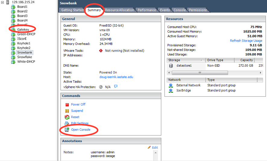
Fig. 47 Selecting Gatekey virtual machine.
Run Firefox in the Gatekey console to access the firewall (Snowbank).

Fig. 48 Gatekey Console
Enter the address of Snowbank,
http://192.168.1.1, in Firefox’s address bar to access the firewall admin console. You will see an admin login for the pfSense firewall (see Fig. 49). The default username is “admin” and the default password is “iseage”.
Fig. 49 Gatekey Console
After you have logged in, you need to select the WAN interface to edit the WAN address and default gateway. See Fig. 50, Fig. 51, Fig. 52, Fig. 53, and Fig. 54 for all of the steps. After selecting the WAN interface, you will see a place to configure the IPv4 address. If you are connecting ISERink directly to the public Internet, this is where you enter the public IP address that you will be using for ISERink. If you are installing ISERink behind a NAT/FW, this is where you enter the private IP address that resides on your NAT/FW network.
Note
The range
192.168.1/24cannot be used since it would conflict with the internal network.Then enter the appropriate IP address for your Internet gateway. Consult your network administrator if you are unsure what this should be, or review “ISERink Internet Access”. Make sure the default gateway box is checked. After entering the new gateway, you need to save the configuration and then apply the changes.

Fig. 50 Select Interfaces
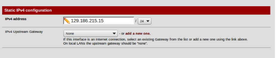
Fig. 51 Enter your WAN IP Address
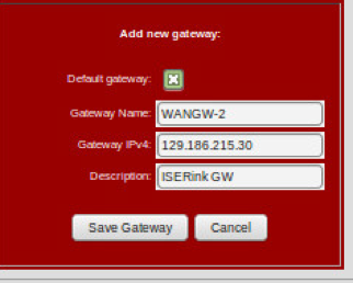
Fig. 52 Add new Gateway
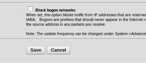
Fig. 53 Keep “Block Bogon Networks” unchecked

Fig. 54 Apply the changes.
After you have configured the WAN address, you can do a quick test to see if it is working by pinging the gateway. You can select that option in the diagnostics menu.
Configure IScorE
Next you will need to configure IScorE to set up the external IP address. First, you will bring up the console window for IScorE. Log in to the IScorE as root, with initial password of “iseage”.
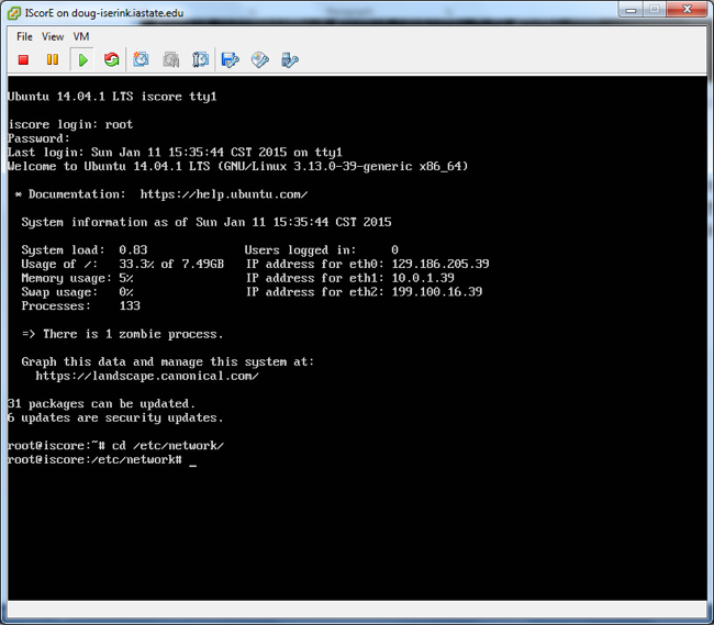
Fig. 55 Login into IScorE
After you have logged in, edit the file
/etc/network/interfaces. You can use one of the editors installed on IScorE (vi,nano) to edit this and other files. You will see a large number of networks defined as shown in Fig. 56. Here is where you will modify IScorE’seth0interface. If you are installing ISERink directly on the Internet, then you will use a public IP address; if you are installing ISERink behind a NAT/FW, then you will be using a private IP address from your NAT/FW network. Under the lineiface eth0 inet static, you will need to modify the lines for address, netmask and gateway to values that match your configuration, as shown in Fig. 56.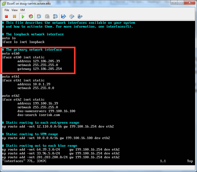
Fig. 56 Editing interfaces
Next we will edit the file
/etc/hostsand replaceiscore.iserink.comwith the FQDN of your IScorE. So for example, you may changeiscore.iserink.comtoiscore.myschool.edu.After you have modified the file, issue the command
rebootand wait for IScorE to restart.After IScore has restarted, you are ready to continue with the IScorE configuration.
Next you will need to configure IScorE to serve the internal DNS entries. From the command line, edit the file
/etc/bind/named.conf.local, as shown in Fig. 57. You will need to change the zone name to match the DNS entry for your IScorE. So for example you will changeiscore.iserink.comtoiscore.myschool.edu.
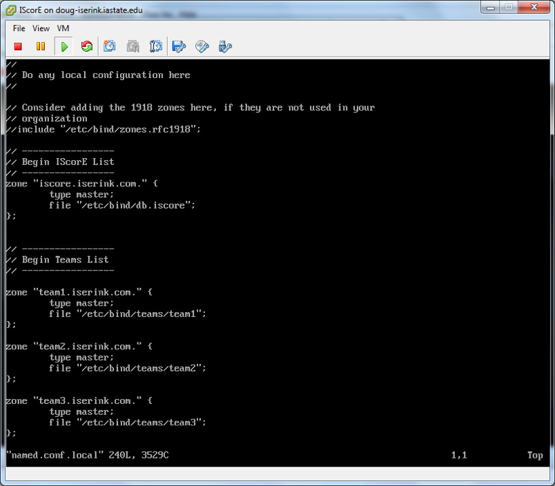
Fig. 57 Change DNS for IScorE
After this step, you can restart bind by typing
systemctl restart bind9.Next, we will change the Django settings file
/var/www/iscore/iscore/settings_local.pyto tell Django what host/domain names that IScorE can serve. Make sure theALLOWED_HOSTSline includes the internal IScorE IP address199.100.16.39, the FQDN of your IScorE and the IP for IScorE that you set on IScorE’seth0, as seen in Fig. 58. For example, you would changeiscore.iserink.comtoiscore.myschool.eduand change129.186.215.26to your IP address for IScorE.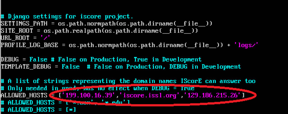
Fig. 58 Changing ALLOWED_HOSTS
After this step, you can IScorE by typing
supervisorctl restart iscore.Next you will need to add an SSL certificate to IScorE. Change into the directory
/etc/nginx/ssland typesh mk_key. It will ask you several questions, including a password for the key, you only need to remember it while running the script. The password for the key is stripped off during the process. Another important field is the “common name” this needs to be the FQDN of your IScorE.After this step, you can restart nginx by typing
systemctl restart nginx.
Configure Keyhole1
- You will need to configure keyhole to resolve the DNS entry for your IScorE.
In order for users inside the Competition Network to be able to access IScorE
using the same domain name as external users, you need to change the file
/etc/namedb/named.confas shown in Fig. 59. First you will bring up the console window for Keyhole1. Log in to the VM as root, with initial password of “iseage”. Edit the file named/etc/namedb/named.confand change the line shown in the figure to match the public DNS name of your IScorE system. After you have changed the file, you can restart named by typing:/usr/local/etc/rc.d/named restart.
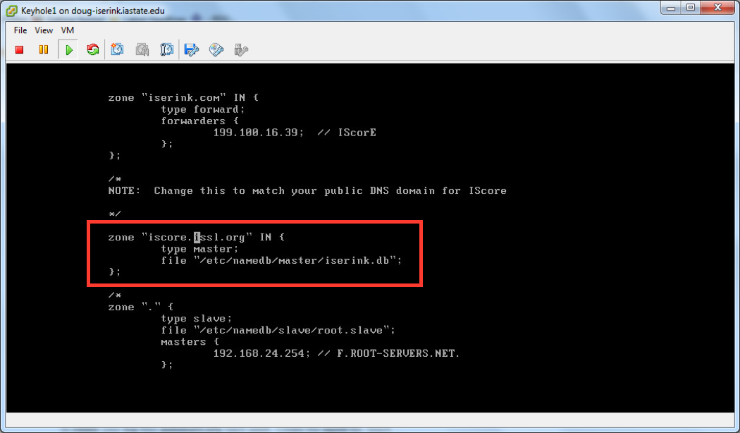
Fig. 59 Changing named.conf
- Next we need to add a line to the file located at
etc/named/master/iserink.db. - Before we can edit this file we have to change its permissions with the following command:
chmod 644 /etc/named/master/iserink.db
- Now edit
/etc/named/master/iserink.dbby adding the following line to the end of the file:
wpad CNAME proxy.iserink.com
- Save your changes and then change the file permissions back with the following line:
chmod 444 /etc/named/master/iserink.db
- (Optional) If you would like to use an internal domain name besides
iserink.com, the configuration for the Squid proxy must be altered. In the
Squid configuration file /usr/local/etc/squid/squid.conf, edit the line
acl local-serverssuch that the desired internal domain(s) are specified. Without configuring this setting, these domains will be proxied to the real Internet.
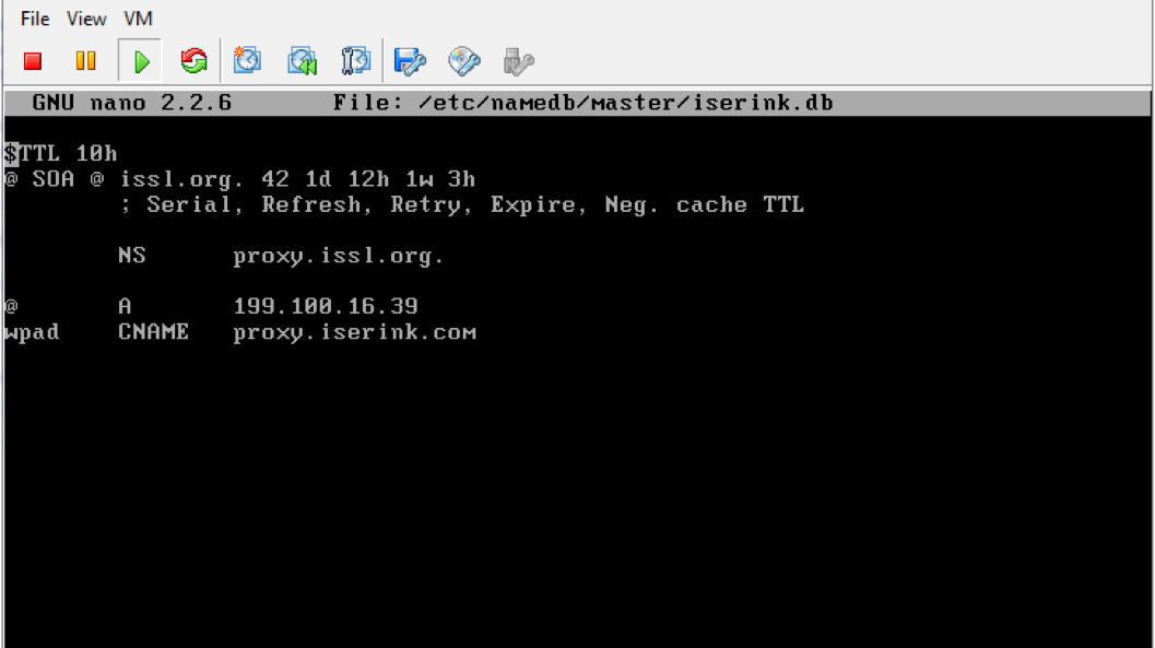
Fig. 60 Changing iserink.db
Configure Snowflake
Snowflake provides a web interface to interact with the ISERink boards and
restart them if necessary. Access to the Snowflake website is done via port
forwarding rules already configured on Snowbank, but you will need to enter the
IP address of Snowbank’s WAN interface into the file
/usr/local/www/apache22/cgi-bin/isecontrol.pl.
Edit the file /usr/local/www/apache22/cgi-bin/isecontrol.pl. Find the line
below and change the IP to match your Snowbank WAN interface IP.
Content=\"0:url=http://129.186.5.153/control/control.shtml\">\n";
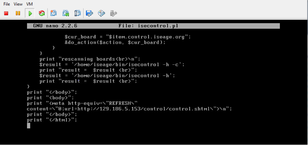
Fig. 61 Changing isecontrol.pl
Final steps
At this point, you should have a functioning ISERink. If you are using IScorE, you will need to add information to your Active Directory server to support team access to IScorE See Setting up AD to support IScorE. To use ISERink, you will need to set up your computers for the teams.
Setting up AD to support IScorE
IScorE is designed to support scoring for cyber defense competitions. IScorE allows various teams to log in and access materials, post reports, and interact with other teams. IScorE uses AD to authenticate the users. The table below shows the various groups and users that need to be added to the ISERINK domain. This section also shows some of the major steps required to setup your AD to support IScorE.
Warning
These instructions assume you are familiar with setting up AD. If you have never installed and configured an AD before, you should refer to materials available from Microsoft and other sources.
| OU | Purpose |
|---|---|
| CDCUsers | Used to organize all Blue users and groups |
| GreenTeam | Used to organize all Green users and groups |
| RedTeam | Used to organize all Red users and groups |
| White | Used to organize all White users and groups |
| AD Group | Usage | OU |
|---|---|---|
| Domain Admins [1] | IScorE superuser account provides access to all aspects of IScorE | Users | |
| CDCUsers | Group used for each group CDC Team X | CDCUsers |
| CDC Team X | Used to group Blue Team members into a team (X is 1 through MAX Teams) | CDCUsers |
| GreenAdmin | Used for the Green Team leader | GreenTeam |
| Green | Group used for the Green Team members | GreenTeam |
| Red | Group used for the Red Team members | RedTeam |
| White | Group for White Team members | White |
| [1] | If you are using an existing AD and you don’t want your existing Domain
modify the settings_local.py on IScorE to match the new group you reated. For
example, you could create a group called CDCAdmins, add this to the users you
want to have superuser access to IScorE and then change the lines in the
IScorE settings_local.py that list “Domain Admins” with “CDCAdmins”. |
| User | Group Membership |
|---|---|
| Blue team member | CDCUser, CDC Team X |
| Green team member | Green |
| Red team member | Red |
| White team member | White |
| Green Leader | Green, GreenAdmin |
Build ISERINK.ORG domain (Optional)
Note
The following instructions are optional and are designed for installations that do not already have a domain controller or want to have a dedicated domain controller for their ISERink installation. If you do decide to install a dedicated domain for ISERink, then we would strongly advise connecting this to the currently unused private network that connects directly to IScorE or the White Network.
Warning
If an existing Active Directory server is being used, this section should be skipped.
When setting up the AD to support IScorE, you need to create the ISERINK.ORG domain. The figure below shows creating a domain within a new forest on an AD that is dedicated to support ISERink (in the next section you will add the groups and users).
- After you have installed Active Directory Domain Services you will need to upgrade your Active Directory server to a Domain Controller. To do this open Server Manager and you will have a notification that says Post-deployment Configuration as seen in Fig. 62.
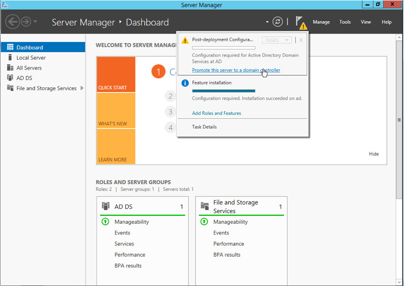
Fig. 62 Server Manager Notification
- In the notification click on the link that says, “Promote this server to a domain controller” this will launch the Active Directory Domain Services Configuration Wizard
- In the Deployment Configurations tab select Add a new forest and type in iserink.org for the root domain name as seen in Fig. 63.
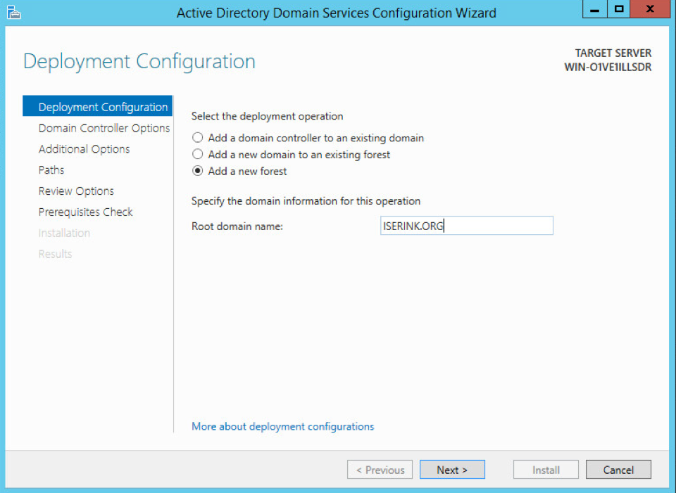
Fig. 63 Deployment Configurations tab
- In the Domain Controller options tab, select the function levels as Windows Server 2012, make sure DNS is unchecked and select a Directory Services Restore Mode password; you can use the table in Appendix A to write down this password. These settings can be seen in Fig. 64.
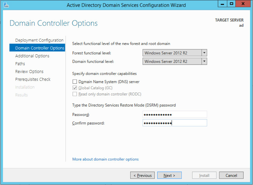
Fig. 64 Domain Controller Options Tab
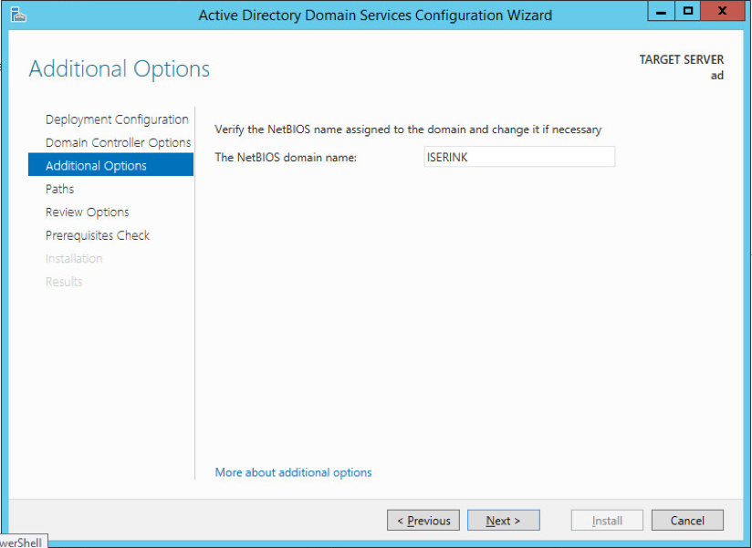
- In the Additional Options tab set the NetBIOS name to ISERINK as seen in Fig. 65. This should automatically populate.
- Leave all setting in the Paths tab as their default settings.
- Review your settings to make sure they are correct, then click install on the final page after your system has verified that all necessary prerequisites are installed.
- Your server should automatically reboot, and your Active Directory is now set as a Domain Controller
After the Active Directory server is completely set up, proceed to Create AD groups and Organizational Units.
Using an existing Active Directory server
If an existing active directory server is being used, it is strongly suggested that you create a new group to be the Administrators for IScorE. Here is an example for how to do this but You are able to organize this in any way to fit the structure of your existing architecture.
- Create a new OU named CDCAdmin
- Inside this OU create a group named CDCAdmins
- Add all users that you would like to have full access to the IScorE admin into this
Create AD groups and Organizational Units
Below are instructions to access a PowerShell script to complete the basic AD setup. The script sets up all Organizational Units and groups but, you will have to add the users yourself.
It is important that you understand the organization to add the users. More details are provided in Create users.
The script is available through SCP on isechest.iac.iastate.edu you will access this using an SCP client on your Active directory server. Download and install WinSCP from www.ninite.com then start WinSCP and log in using the credentials you were provided to download the Virtual Machine images.
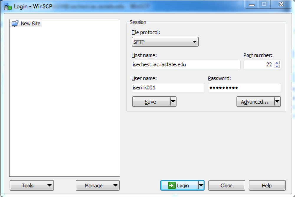
Fig. 66 WinSCP Login
Navigate to /usr/home/downloads/ISERink/scripts/ and download
active_directory_setup to your desktop. Right click on the file and select
Run with PowerShell.
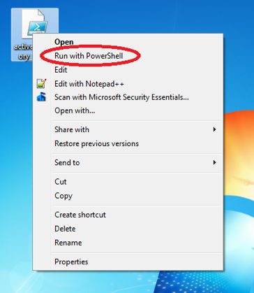
Fig. 67 Run active_directory_setup
If you launch “Active Directory Users and Computers” you should now see all the users, groups, and Organizational units.
Create users
Create new user
To add a new user, right-click on the Organizational unit you wish to add a user to and select new and then user.
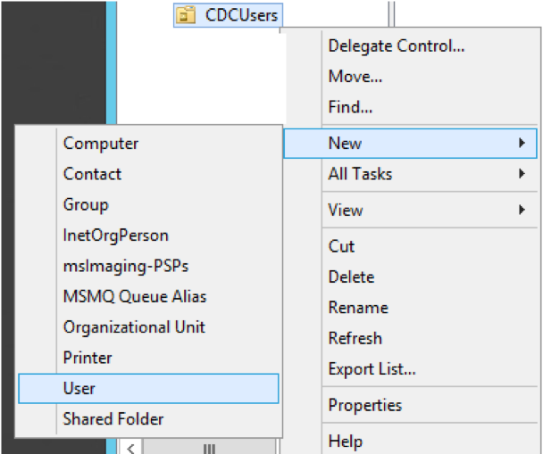
Fig. 68 Add New User
You will then see a prompt to set the users data. Enter all of this information: at minimum you must enter first name, last name, user, login name, and password.
Add User to Desired Groups
There are four groups of users for IScorE. All users must be set up in one of the ways described below depending on what actions they should be able to perform. To add a user to a group right click on the user and select “Add to a Group…” then enter the group name and hit OK. For details on what groups to add users to, see the discussions below.
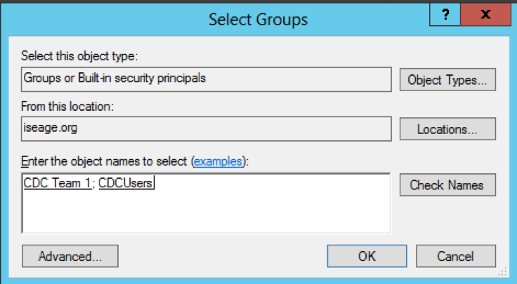
Fig. 69 Add User to Group
Groups
Blue User
Blue users are a member of CDCUsers and “CDC Team X” where X is the user’s team number. The CDCUsers OU structure can be seen in the diagram in Fig. 70. Each of these users can log into IScorE and perform actions for their team such as view team specific information, download flags, and submit documentation.
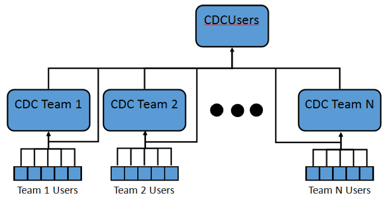
Fig. 70 CDCUsers Organizational Unit Diagram
Green User
Green users are a member of the group Green. The GreenTeam OU structure can be seen in Fig. 71. Green team users can log in to IScorE and perform tasks necessary for grading teams such as viewing all teams’ team specific info, grade anomalies and, grade documentation.
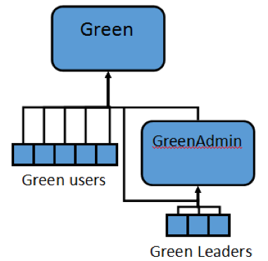
Fig. 71 GreenTeam Organizational Unit Diagram
Green Admin
Green Admins are members of the group GreenAdmin and Green. The GreenTeam OU structure can be seen in Fig. 72. Green Admins can log in to IScorE and perform tasks necessary for grading including creating usability checks and, creating anomalies.

Fig. 72 GreenTeam Organizational Unit Diagram
Red User
Red users are a member of the group Red. The RedTeam OU structure can be seen in Fig. 73. Red team users can log in to IScorE and perform tasks necessary for attacking and scoring the teams such as submitting a captured flag, planting a flag and, grading earnbacks.
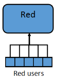
Fig. 73 RedTeam Organizational Unit Diagram
White User
White users should be a member of Domain Admins and White. The White OU structure can be seen in Fig. 74. White users can log in and see all areas and perform all actions in IScorE. This includes editing settings, creating new competitions, and overriding team scores.
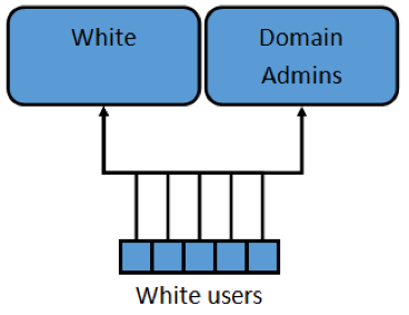
Fig. 74 White Organizational Unit Diagram
Configure IScorE
- Log in to the IScorE as root, with initial password of “iseage”.
- Next you will need to configure IScorE to query the Active Directory that you
just set up. From the command line edit the file
/var/www/iscore/iscore/settings_local.py - In the line
AD_DNS_NAME = '129.186.5.162'replace 129.186.5.162 with the IP address of your Active directory server, as seen in Fig. 75. - If an existing active directory server is being used and you don’t want your
domain admins to have Admin status on IScorE, you can replace Domain Admins
in the line
AD_MEMBERSHIP_ADMIN = ['Domain Admins']to the name of the group you created earlier.
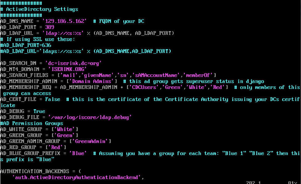
Fig. 75 IScorE LDAP Setup